Known acquisition geometry
PB-GS assumes calibrated detector geometry and known continuous sensor trajectories. The benchmark is synthetic and controls the optimization setup to isolate projection-dependent quality and cost.
Department of Aerospace Intelligent Science and Technology, School of Astronautics, Beihang University
State Key Laboratory of Virtual Reality Technology and Systems, Beihang University
Corresponding author: Zhengxia Zou
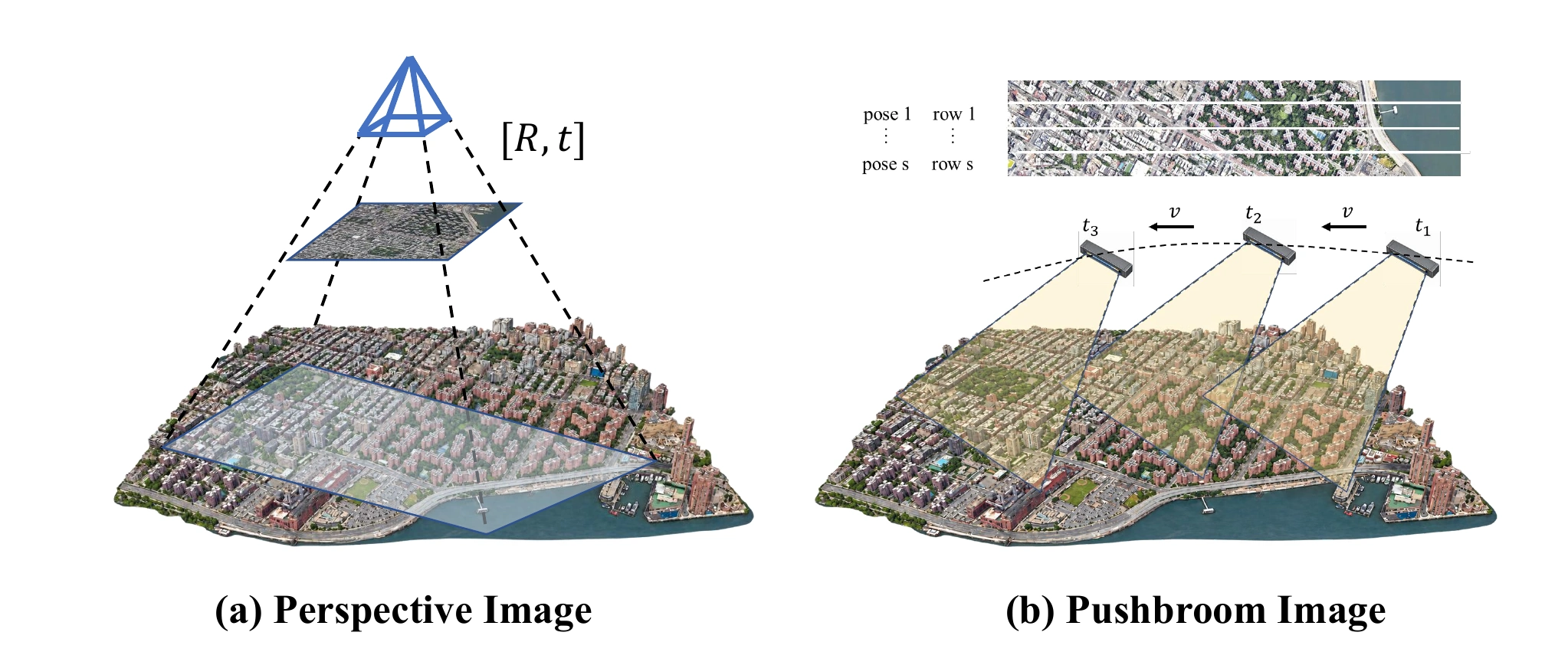
Reconstructing 3D Gaussian scenes from native pushbroom imagery.
Line-array cameras capture pushbroom images line by line as they move. Modeling this geometry in 3DGS requires resolving row–pose coupling and acquisition-dependent Gaussian footprints.
High-fidelity 3D scene reconstruction is essential for remote sensing and Earth observation. Pushbroom sensors are widely used in airborne and satellite imaging; however, when integrated with 3D Gaussian Splatting (3DGS), their inherent line-by-line acquisition geometry lacks rigorous geometric formulation. To bridge this gap, we present PB-GS, an acquisition-aware Gaussian splatting framework for scene reconstruction directly from native pushbroom imagery. To resolve the circular dependency between the projected position and the observing pose in pushbroom imaging, we model the native projection as an implicit geometric constraint and introduce a fast Newton-based solver to dynamically determine the precise acquisition state. Considering that the 2D projected footprints of Gaussian primitives undergo deformation induced by the continuous pushbroom process, we propose the PB-EWA formulation to encode these acquisition-dependent variations, which seamlessly preserves efficient whole-image rasterization. Furthermore, we establish a unified orthographic rendering pipeline to generate true digital orthophoto maps (TDOMs) and digital surface models (DSMs), effectively bridging 3DGS with practical remote sensing product generation. Experiments demonstrate that the proposed pushbroom projection and PB-EWA model yield significantly higher sensor simulation fidelity and 3D structural accuracy, achieving reconstruction quality comparable to an explicit row-wise reference at a substantially lower computational cost. By successfully connecting physical remote sensing camera models with efficient differentiable reconstruction, PB-GS establishes a rigorous and scalable paradigm for large-scale pushbroom photogrammetry and geospatial mapping.
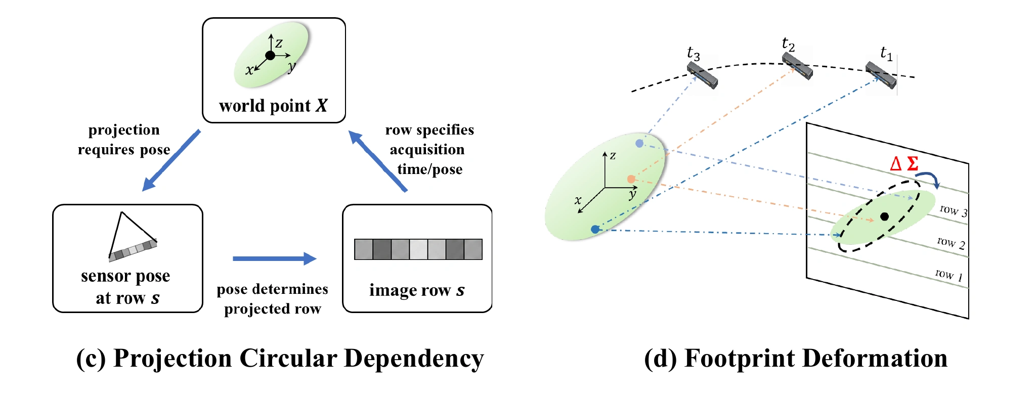
A line-array camera records one detector line at a time as the platform moves. Each image row therefore has its own observing pose. This creates two coupled problems: the projected row and pose must be solved together, and the Gaussian footprint must account for acquisition changes across its spatial extent.
Given native pushbroom observations, calibrated detector geometry, and known trajectories, PB-GS first solves each Gaussian’s observing row and constructs its acquisition-aware footprint. Whole-image rendering then supports scene optimization. The reconstructed scene is finally queried orthographically to generate TDOMs and DSMs.
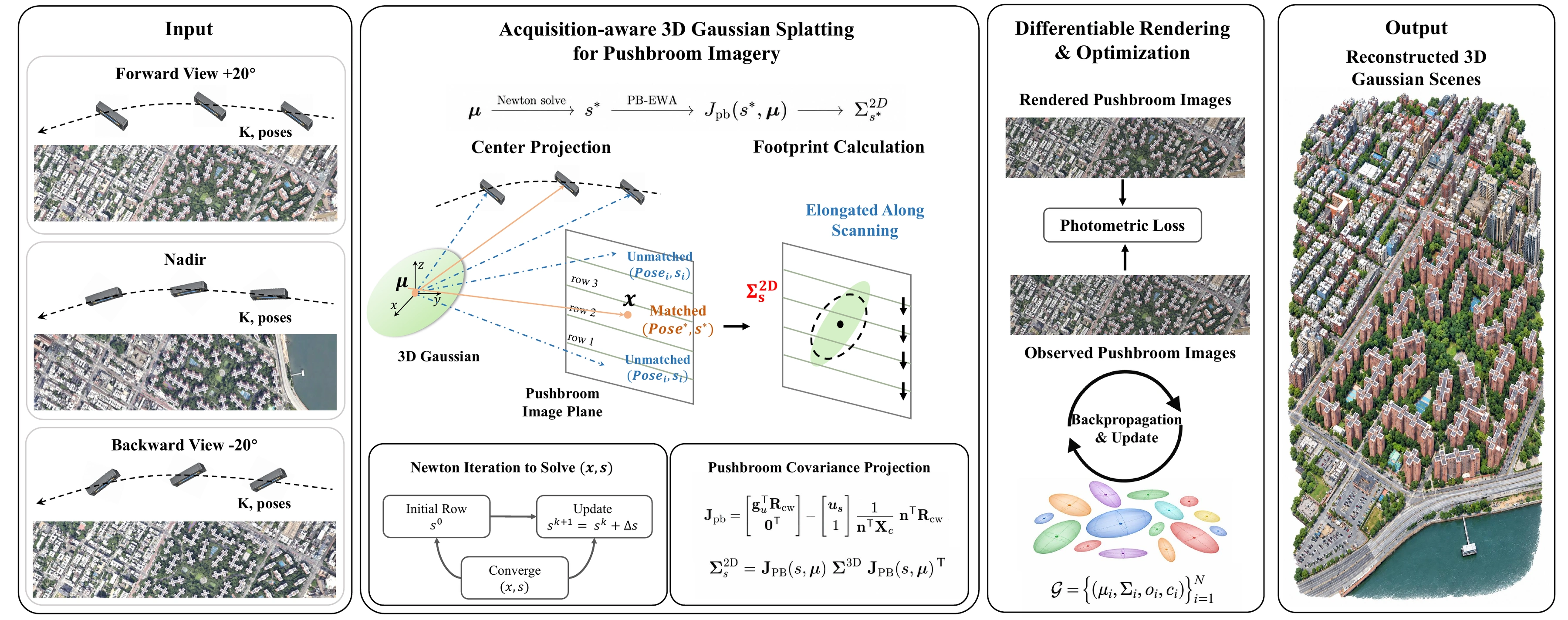
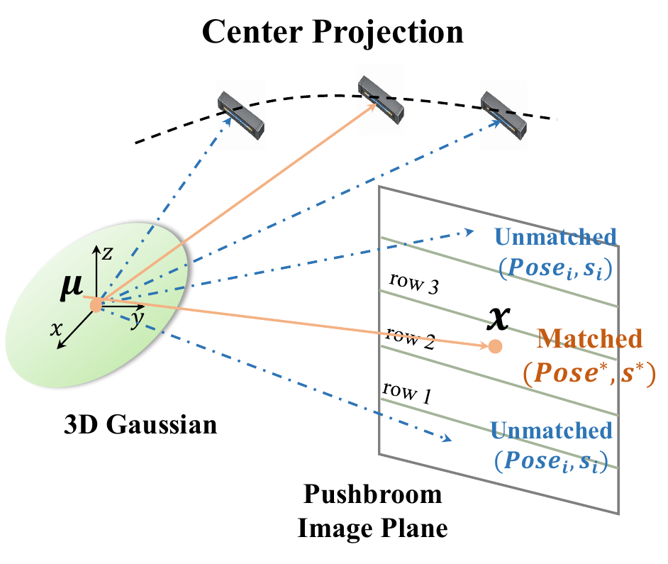
For a Gaussian center μ, the correct row s* is the root of the moving scan-plane constraint h(μ, s*) = 0. The candidate row determines the sensor pose, which in turn determines the residual.
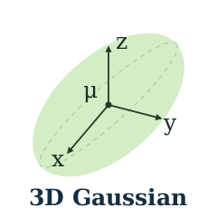
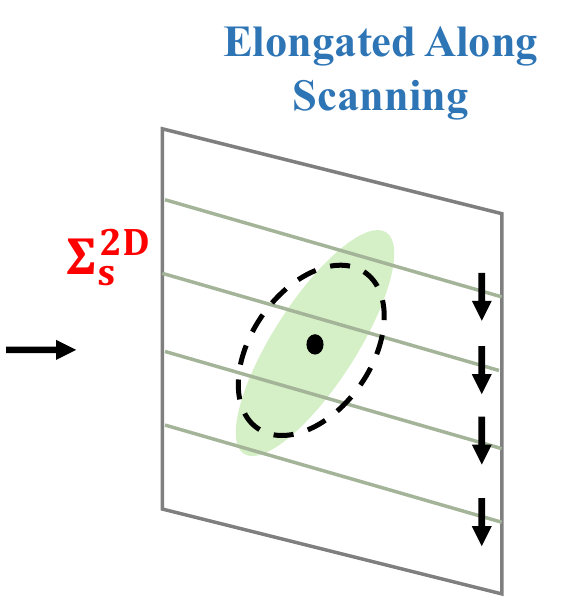
A Gaussian spans multiple acquisition rows. PB-EWA captures the resulting pose variation through the acquisition sensitivity sX = −hX / hs, then combines it with the fixed-pose differential J0.
The full Jacobian propagates the 3D covariance into the 2D footprint. A low-pass term, εf = 0.3 pixel², regularizes it for rasterization.
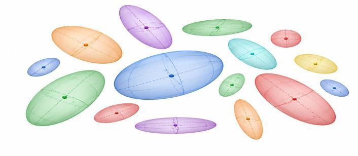
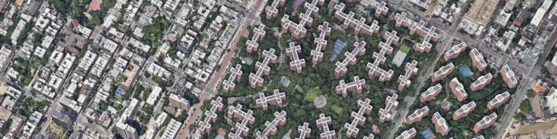
A shared tile-based rasterizer renders each full pushbroom image. The L1 and SSIM loss updates the Gaussian scene through differentiable projection and rendering, while detector calibration and trajectories remain fixed.
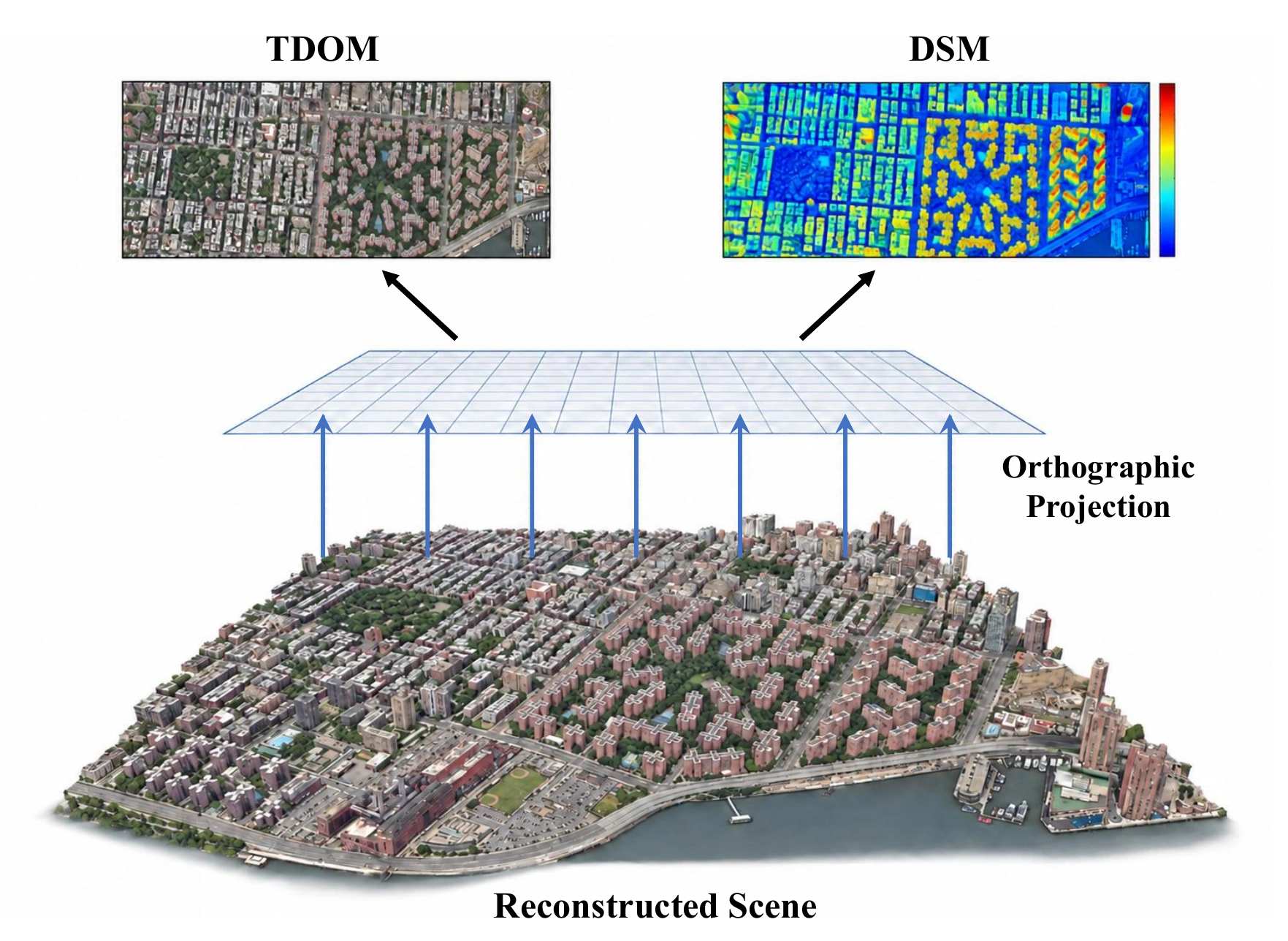
Project the optimized scene onto a north-up orthographic grid. The same normalized compositing weights produce TDOM colors and DSM elevations, with no further scene optimization.
We evaluate how faithfully PB-GS reconstructs unseen pushbroom views and produces orthographic maps and surface models. Eight synthetic urban scenes provide a controlled comparison with camera approximations and explicit row-wise rendering, using the same scene representation and optimization setup.
Held-out pushbroom observations test how well each projection model captures native line-array imaging geometry. PB-GS achieves image quality close to explicit row-wise rendering across eight synthetic urban scenes.
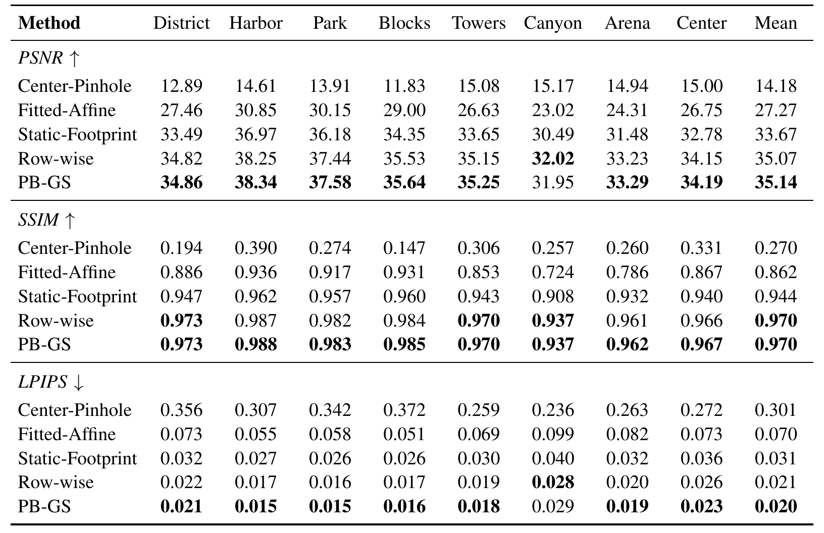
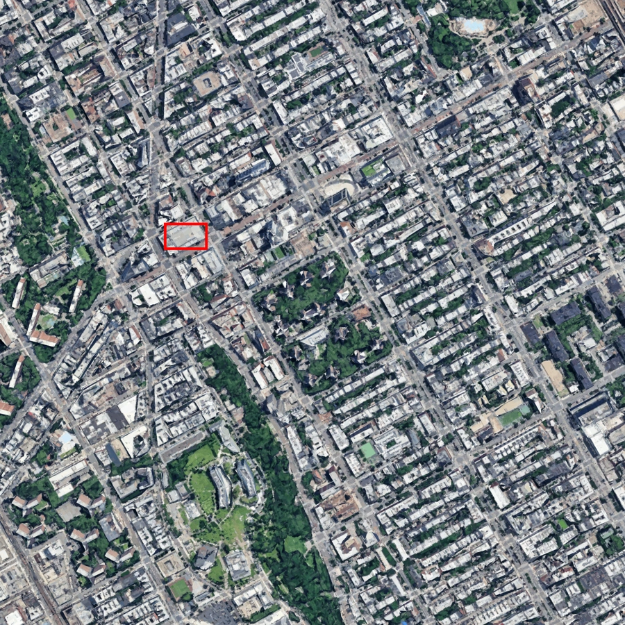
Each red box locates the same local region across the six comparison panels. Select a scene, then open any image to inspect it.
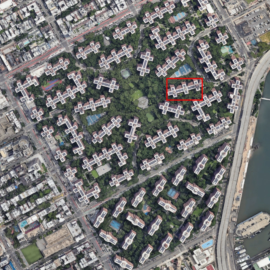
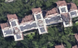
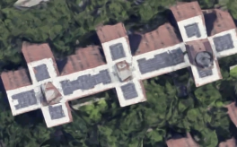
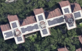
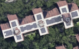
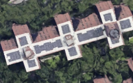
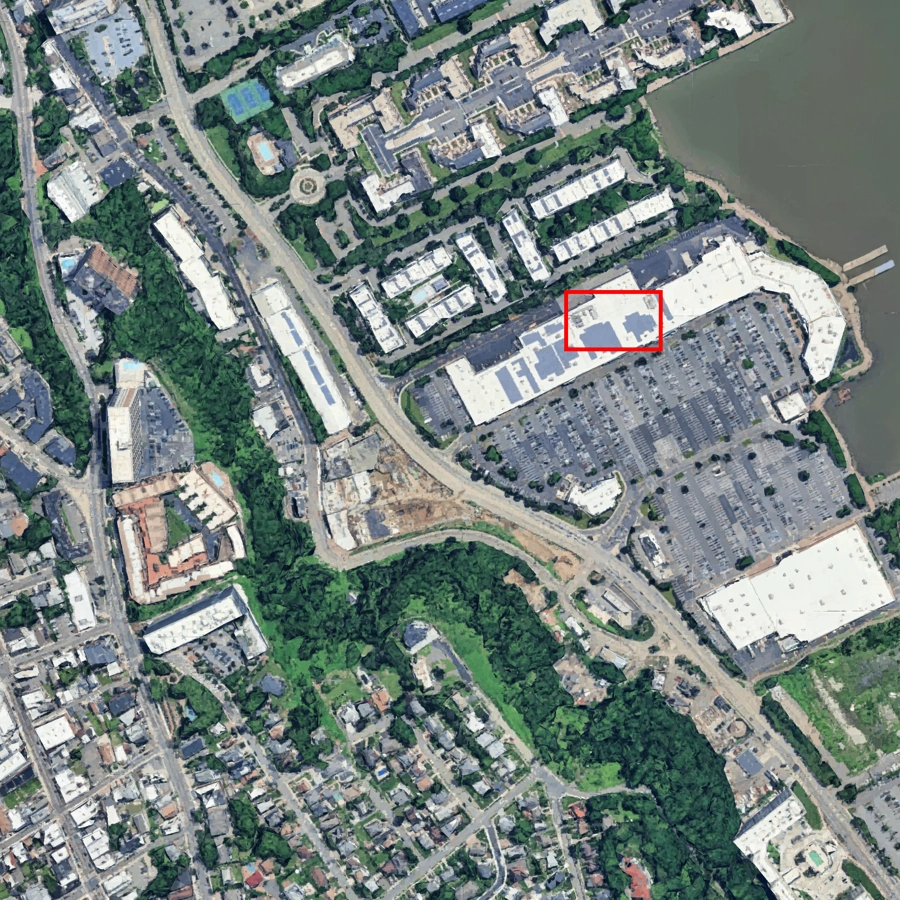
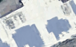
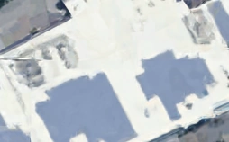
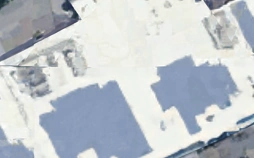
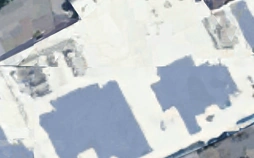
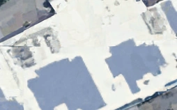
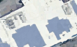
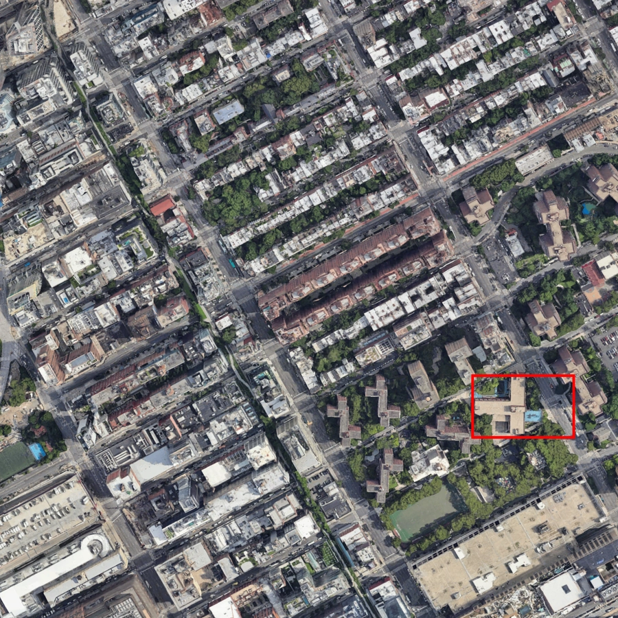
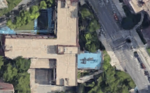
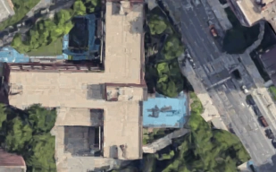
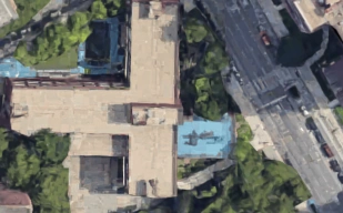
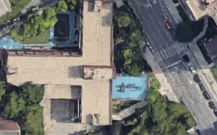
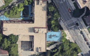
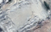
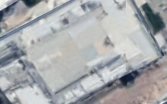
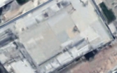
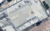
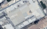
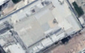
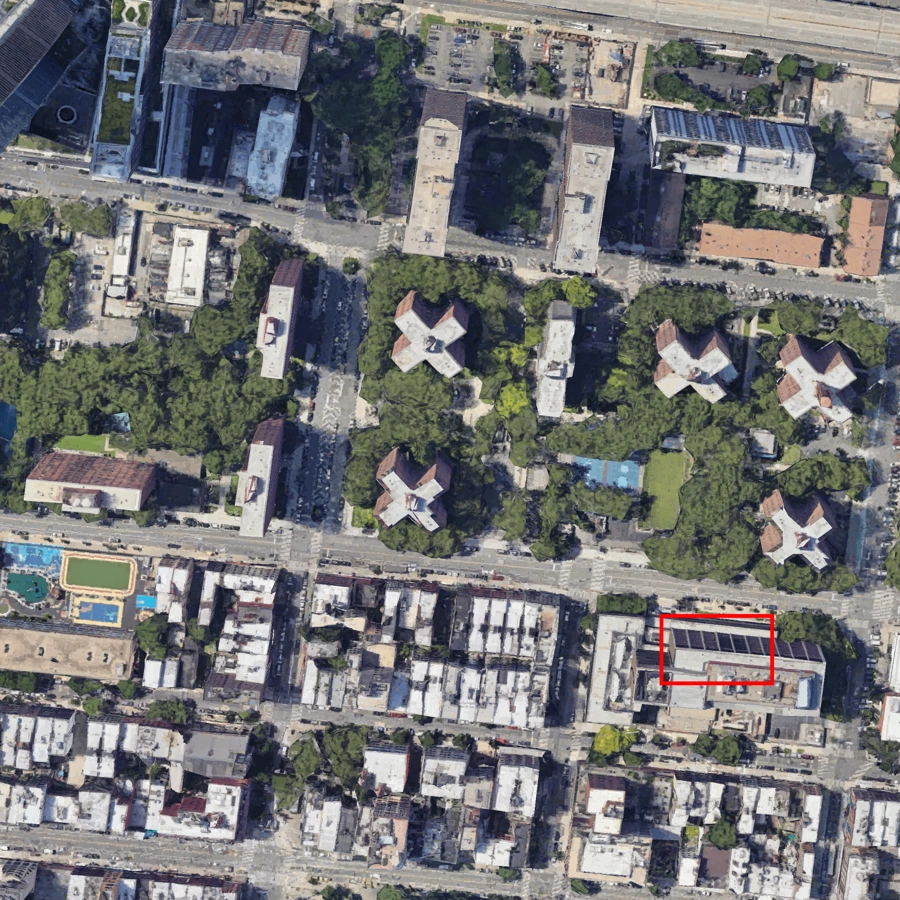
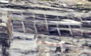
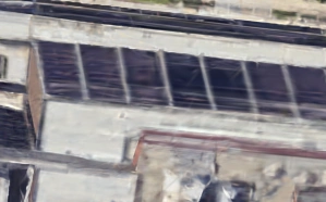
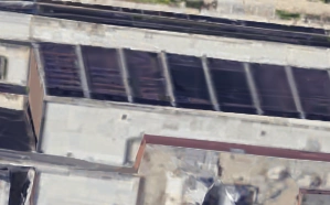
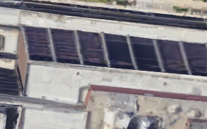
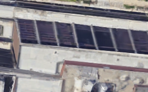
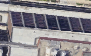
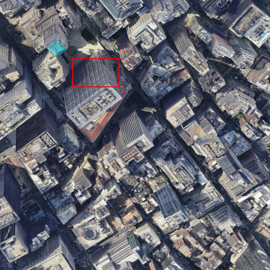
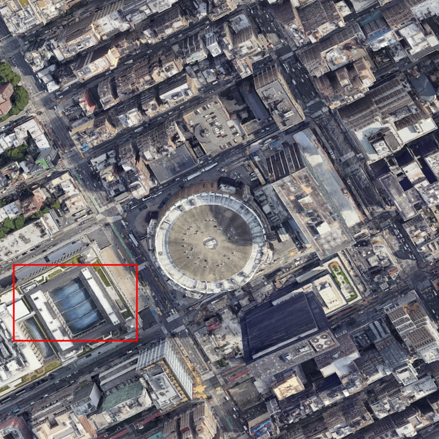
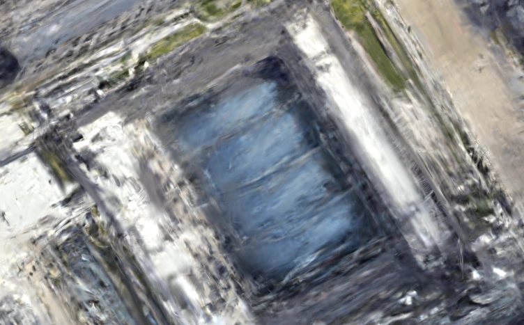
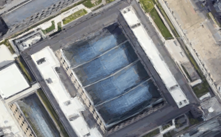

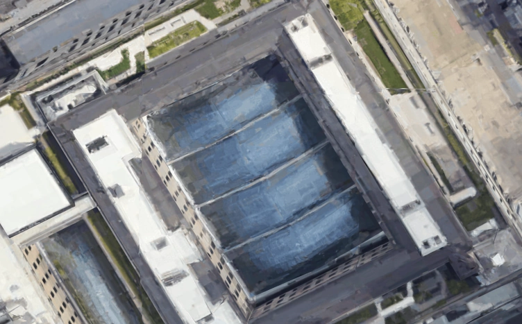
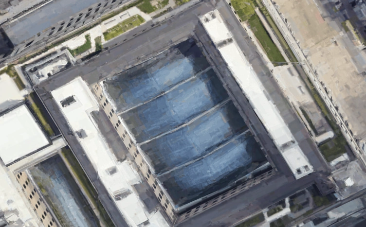
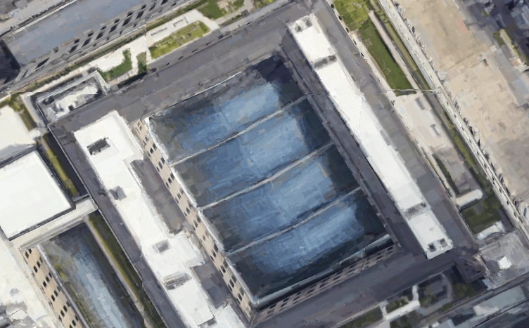
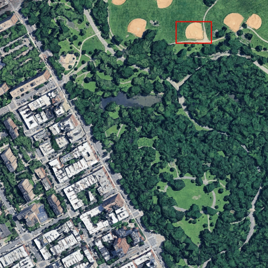
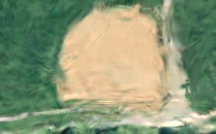
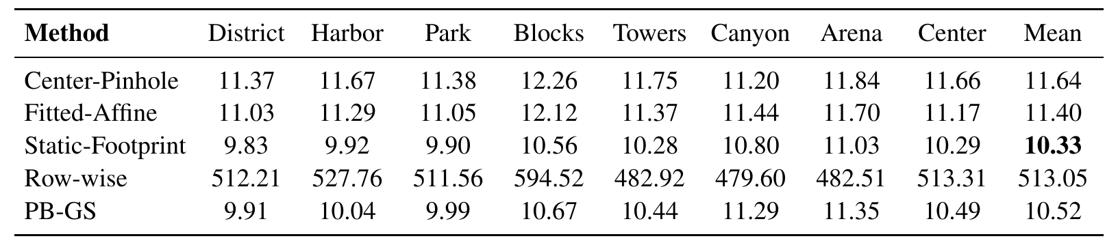
PB-GS approaches the row-wise reference across the benchmark; individual metrics vary by scene. On Canyon, Row-wise has slightly higher PSNR and lower LPIPS.
PB-GS incorporates acquisition geometry before rasterization, allowing the scene to be fitted with efficient whole-image rendering. It reduces the repeated work of explicit row-wise rendering while maintaining comparable reconstruction quality.
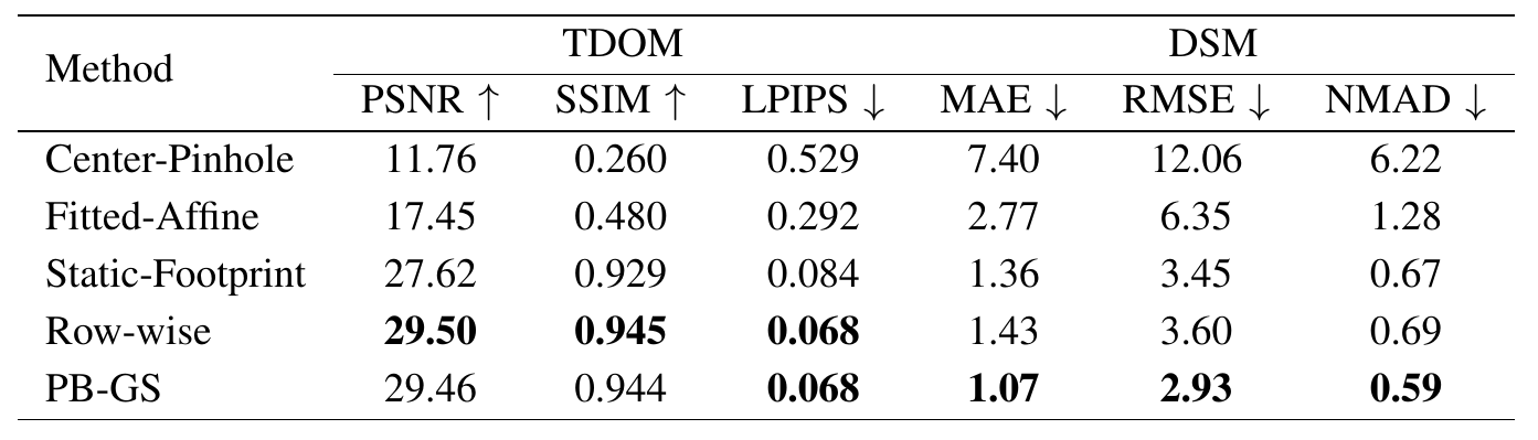
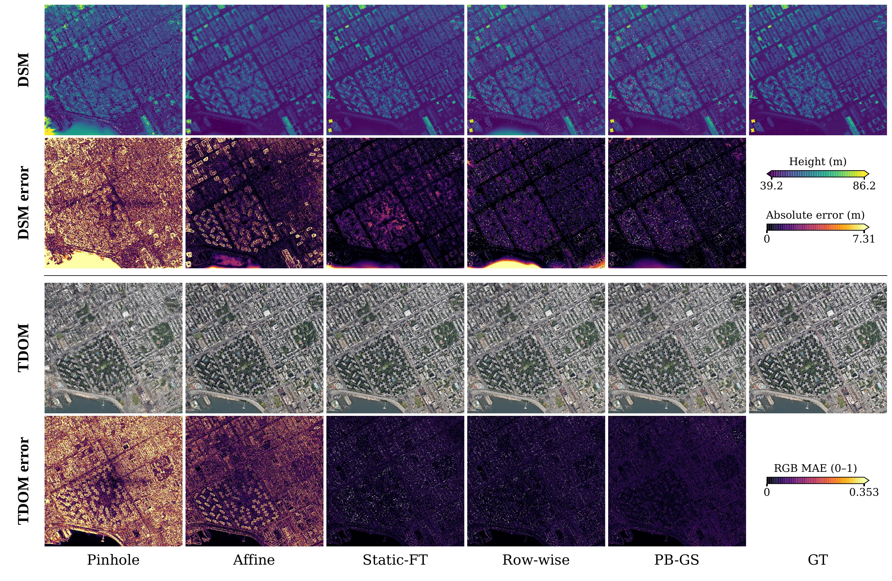
The reconstructed scene supports both orthophoto rendering and elevation recovery. In the reported orthographic evaluation, PB-GS obtains the lowest DSM errors among the compared models, while TDOM quality remains close to the explicit row-wise reference.
PB-GS assumes calibrated detector geometry and known continuous sensor trajectories. The benchmark is synthetic and controls the optimization setup to isolate projection-dependent quality and cost.
Footprints use a first-order local projection differential. Depth ordering and view-dependent appearance use the Gaussian’s center row, rather than being reevaluated at every row across its footprint.
Illumination changes, shadows, and pose uncertainty require additional treatment. Validation on real pushbroom imagery remains necessary to assess performance under these conditions.